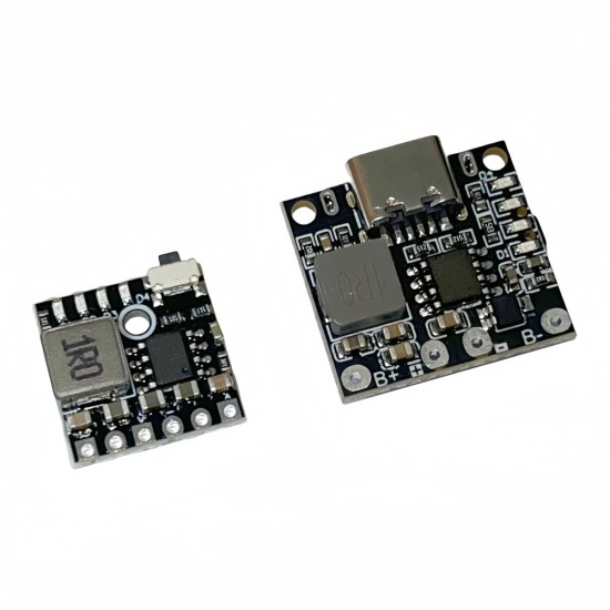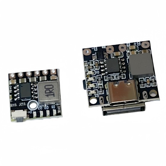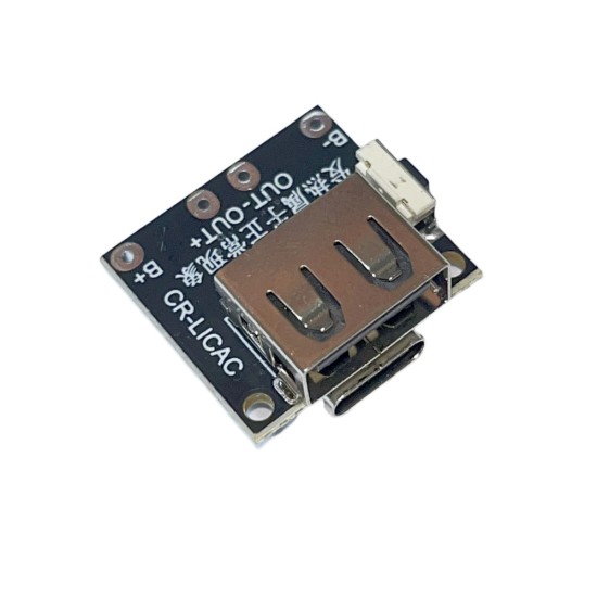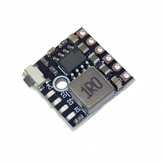


3.7V 4.2V 18650 lithium battery charging and voltage voltage power board protection 5V/2.4 charging and discharge integrated module
2A synchronous switch efficient charging
2.4A maximum output current
Output fixed often open 5V
5V output support line loss compensation
Support the side filling
4 LED power display
Standby power consumption is less than 150 μA battery overvoltage, overcharge, overlap, and flow discharge protection
Increase the following characteristics with interface models
Double -layer battery protection
C -port input charging
Optional USB output port
Mobile phone charging current intelligent recognition DCP
Automatically detect mobile phone insertion and pull out
Definition without USB module wiring.
Vin 5V: Module power supply 5V input positive pole
Out 5V: Module 5V output positive electrode
BAT: Module connect the battery positive pole point
GND: Module input, output, battery end negative pole.All GND line connect
With USB:
Type-C interface: module 5V power supply input interface USBA interface: module 5V output interface, can be charged with mobile phone and other power supply OUT+: module 5V output positive welding point
OUT-: Module 5V output negative pole welding point
B+: module connection battery positive welding point B-: module connection battery negative pole welding point
Note: The above two module keys are only turned on when the LED indicator light is destroyed, and it cannot control the input and output or turn off the LED indicator light.
Precautions
After receiving the motherboard, first test the charging header test, watch the LED lights bright, the normal LED light will light up in order. If there is an exception, please contact the customer service first.
In normal application, the battery must be welded, (the wires are not power supply), the battery is reversed, and the motherboard must be burned.Note.
The battery and motherboard cable should not be too thin, as thicker as possible.Can pass 5A current.You can't weld too long.
The battery can only be connected (the number of parallel connections is not limited), and cannot be connected in series.
Make sure that the battery is good. If you charge the battery, the phone cannot be discharged when it is charged. Most of the battery is scrapped.
If the battery comes with a protective board to ensure that the protection of the protective board is greater than 5A, otherwise the protective board will be removed, otherwise the discharge may exceed one or two and the protective output.
The board must be burned.Burning ICs will have traces.This happens only when it is reversed.So the consequences of the counter -connection are not assumed here.For example, if the chip is destroyed or burned off, the main control chip will burn obvious traces, and it is a problem with the use of 100 % to protect the chip. Do not pull the skin at that time.
When accessing the battery, you must determine the 3.7V lithium battery, and you cannot.Make sure that the battery is not connected in series, otherwise the battery access voltage may burn the board if it is higher than 4.5V
All the power supply will heat up. This is common sense of electronic. Everyone's products are the same. If it is not heated, the current will not be limited to 2.4A. It is not very good to make a 10A and 100A.Use the mainstream chip of large manufacturers, and use good efficiency and use.
The input and output switch takes time. Within about 1 second, all the modules cannot completely replace the UPS module, please make notice.
| Product Attributes | |
| Brand | Other/Other |
| Output Voltage | 0.1 |
Unlimited Blocks, Tabs or Accordions with any HTML content can be assigned to any individual product or to certain groups of products, like entire categories, brands, products with specific options, attributes, price range, etc. You can indicate any criteria via the advanced product assignment mechanism and only those products matching your criteria will display the modules.
Also, any module can be selectively activated per device (desktop/tablet/phone), customer login status and other criteria. Imagine the possibilities.
$1.02
Price in reward points: 1
- Stock: In Stock
- Model: ULZW1302
- Weight: 0.10kg


