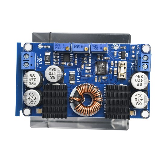
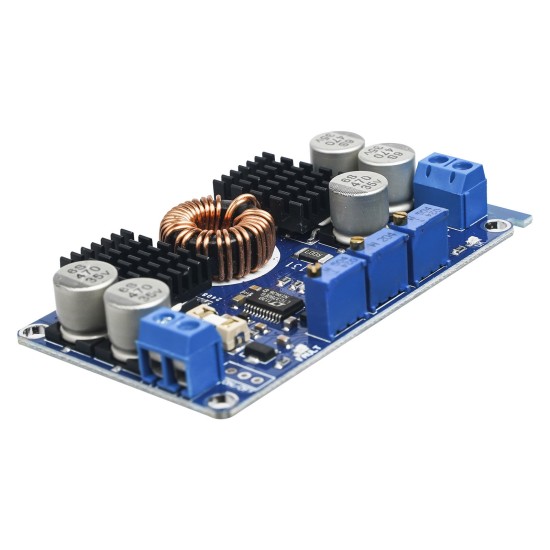
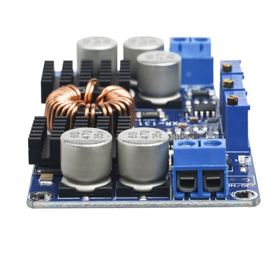
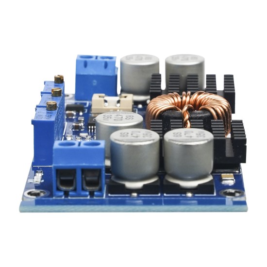
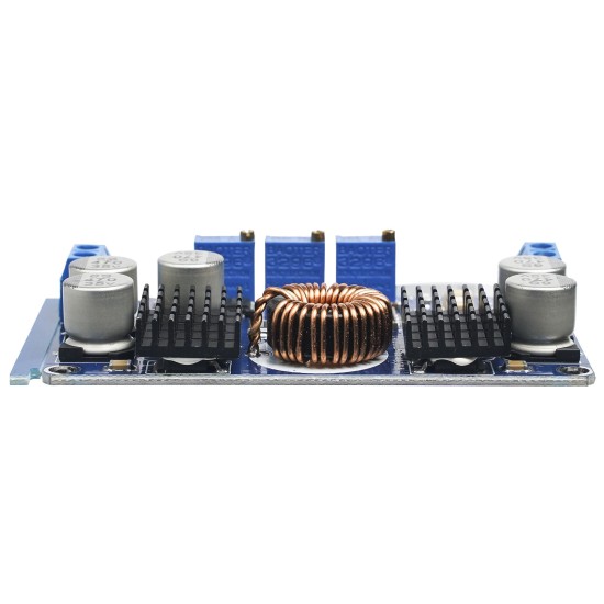


DCDC LTC3780 Automatic Poor Pressure Solar Voltage Stabilizer Constant Powder Constant Power Module Super Book
Introduction to synchronization rectification technology:
The same step rectifier is a new technology that uses a special power MOSFET with extremely low -state resistance to replace the rectifier diode to reduce the rectification loss.It can greatly improve the efficiency of the DC/DC converter and there is no dead zone voltage caused by the voltage of the Schottki power.The power MOSFET is a voltage control device, which has a linear relationship when it is turned on.When using the power MOSFET as a rectifier, the gate voltage is required to be synchronized with the phase of the rectifier voltage to complete the rectifier function, so it is called synchronous rectifier.Synchronous rectification technology is to greatly reduce the rectification loss of the output of the switching power supply, thereby improving the conversion efficiency and reducing the power supply itself.
This power supply is a high -efficiency voltage voltage power module. When the input voltage is lower, higher, and equal to the output voltage, the output voltage can remain stable and unchanged.For example, when the output is set to 12V, then when the input voltage changes between 5 and 32V, the output voltage voltage is unchanged at 12V.This module has a complete protection function and can be used in solar charging.
Advantages:
The circuit board adopts a 1.6 thick gold plating process;
The input uses a replaceable insurance tube to protect the power supply and equipment;
The entire version of the electrolytic uses imported original patch, low resistance, and high -frequency capacitors, so that the ripples are reduced to the freezing point;
IC uses imported originals;
Constant pressure, constant current, and under pressure protection (MPPT is more suitable for solar charging)
Output error indicator light, the output voltage drift is too serious, short circuit and other failures are on;
Oxidation heat dissipation tablets heat dissipation, the heat dissipation effect is better than the original aluminum sheet;
The inductance uses iron and silicon aluminum, and the heat is smaller;
You are welcome to buy and use our voltage module. Please read the following instructions carefully. Otherwise, the company will not be warranty or replaced due to damage caused by improper use.
This module belongs to the automatic lifting voltage power supply. When the input voltage is lower than, higher than, equal to the output voltage, the output voltage can remain stable and unchanged.For example, when the output is set to 12V, when the input voltage changes between 5 and 32V, the output voltage voltage is unchanged at 12V;Pressure and short -circuit protection; all components can reach industrial -grade applications; they can be perfectly applied to various occasions, such as charging, high -power LED driver, equipment power supply, vehicle power supply, etc.
Electric parameters:
1. Input voltage: DC5-32V, it is recommended to use voltage above 10V or more
2. Output voltage: DC1V-30V continuous adjustment;
3. Output current: 10A (MAX) within 7A;
4. Output power: long -term 80W, peak value of 130W, please strengthen heat dissipation after 80W;
5. Output lines: 50mV (12V to 12V, 5A measured);
6. Enter anti -connection protection: None, if necessary, please connect the Xiaotki diode in the input end;
7. Output anti -inverted irrigation: None, if it is used for battery charging or load is a self -powered emotional load, please connect the Xiaotki diode in series at the output end;
8. Size: 77.6*46.5*15mm
9. Short -circuit protection: Yes;
10. Weighing about 45 grams;
Debug method:
1.Method of battery under pressure protection adjustment method: (take 12V lead -acid battery settings 10V under pressure protection, turn off output as an example)
Input the adjustment of the voltage voltage power supply to 10V, adjust the underwriter protection potentiometer (clockwise increases, and decreases counterclockwise) until the fault indicator light (red light) is on, that is, the settings are successful; so when the battery discharge to 10V, when the battery discharge to 10V,The power supply will be automatically cut off to protect the battery from being damaged.
Note: If it is not a battery power supply, you can not set up;
2. Output voltage adjustment method: Input the power supply (the voltage is higher than the low -voltage protection value), the red light is not bright, the blue light is on, the output is connected to the universal meter, and the output voltage potentiometer is adjusted (clockwise increased, and the counterclockwise reduction is reduced).Until the required voltage;
Note: Normally the red light is not bright, the blue light is on, otherwise there is a fault. Input input -under pressure protection, output overcurrent protection, and short -circuit protection of the output.
3. Output current adjustment method: (take 12V input to charge 12V lead -acid battery, charging current 5A as an example)
Input connected to the 12V power supply, output and connect the current meter (red table pens are connected to the output, the black table pen is connected, and the output is directly connected. It is recommended to use a current meter above 15A to prevent burning insurance), adjust the constant current potentiometer (clockwise increased, inverse counterclockwise, inverse inverse of countermeasuresTime clockwise), until the value of the current meter display is 5A, remove the current meter, and connect to the battery to charge normally.
Note: If it is used for constant voltage equipment, you only need to set the maximum output current.
| Product Attributes | |
| Brand | none |
Unlimited Blocks, Tabs or Accordions with any HTML content can be assigned to any individual product or to certain groups of products, like entire categories, brands, products with specific options, attributes, price range, etc. You can indicate any criteria via the advanced product assignment mechanism and only those products matching your criteria will display the modules.
Also, any module can be selectively activated per device (desktop/tablet/phone), customer login status and other criteria. Imagine the possibilities.
$6.07
Price in reward points: 6
- Stock: In Stock
- Model: ULMU1217
- Weight: 0.04kg
Available Options
This product has a minimum quantity of 10


