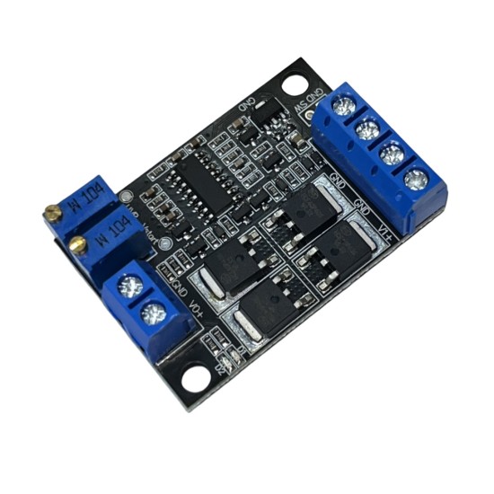


Second Road DC Power Switching Module Two -way low -voltage difference Ideal diode 15A UPS uninterrupted power supply
Features
Work voltage range: 6 ~ 36V.
Maximum output current: low power version 8A, high power version 15A.
Module self -consumption is about 6mA
Using ultra -low power consumption 8 -bit MCU as the main control, the switch is quickly and accurate.
Use high -power low loss MOS tube
2 power supply indicators on the board, which can understand the power supply status in real time.
The switching time is about 0.1ms.
Severe precision multi -circle potentiometers can freely adjust the main power switching voltage and restoration voltage, which is convenient for various voltage occasions.
The main power supply voltage can be higher than or lower than the auxiliary power voltage.
The module does not have the charging function, and the main power supply cannot charge the sub -power supply.
Wiring method: lock line terminal
Size: 46x32x15mm long x width x height.
Work temperature: -40 ~+105 ℃
The actual measurement voltage is as follows (test voltage: 12V)
Point instructions:
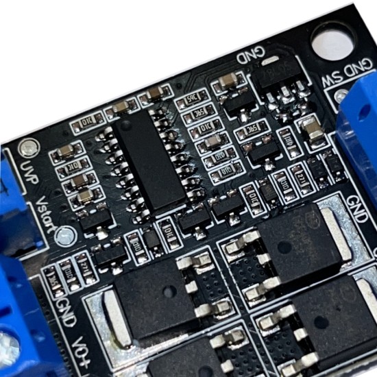
Main power input positive pole
Main power input negative (ground line)
Backup power input negative (ground line)
Backup power input positive pole
Output negative (ground line)
Output positive pole
Indications:
D1: Red light, the main power supply V1 is bright when the power supply is available.
D2: Green lights, the auxiliary power supply V2 is bright, and the main power V1 is destroyed.
Potentiometer:
VR1: Main power switching voltage regulator potentiometer.When the voltage of the main power supply is lower than the setting of the VR1, immediately turn off the main power supply and switch to the backup power supply power output.
The main power switching voltage VUVP is 5 times the test point TP1 voltage, and the test calculation is pressed:
Vuvp = vtp1 × 5 (v)
For example, when regulating the potentiometer VR1, the TP1 voltage is 2V, the switch voltage VUVP = 2 × 5 = 10 (v).When the V1 voltage of the main power supply is lower than 10V, immediately cut off the main power supply and switch to the backup power supply.The default delivery voltage is 10V.
VR2: Main power resume voltage VSTART regulating potentiometer.When the main power supply voltage is higher than the set voltage set by VR2, the backup power supply is immediately turned off and returned to the main power supply output.
The main power recovery voltage VSTART is 5 times the test point TP2 voltage.
Vstart = vtp2 × 5 (v)
For example, when regulating the potentiometer VR2, the TP2 voltage is 2.2V, then the main power recovery voltage VSTART = 2.2 × 5 = 11 (V).When the main power supply voltage is higher than 11V, switch to the main power supply again, and cut off the backup power supply at the same time.The default delivery voltage is 11V.
SW: The output power switch, the external connection switch controls the shutdown and opening of the output.
Open: Open the output.
Short circuit: Close the output.
Note:
It is necessary to ensure that the recovery voltage is higher than the switching voltage, otherwise unexpected phenomena may occur such as switching abnormal
After switching to a sub -power supply, the main power supply voltage is more than 3 seconds before switching to the main power supply.
Both the test point TP1 and TP2 positions are next to the potentiometer, both of which are the ground voltage.Main power, auxiliary power supply, output co -land.
| Product Attributes | |
| Brand | Other/Other |
| Output Power | 0.1 |
Unlimited Blocks, Tabs or Accordions with any HTML content can be assigned to any individual product or to certain groups of products, like entire categories, brands, products with specific options, attributes, price range, etc. You can indicate any criteria via the advanced product assignment mechanism and only those products matching your criteria will display the modules.
Also, any module can be selectively activated per device (desktop/tablet/phone), customer login status and other criteria. Imagine the possibilities.
$13.50
Price in reward points: 13
- Stock: In Stock
- Model: ULGU1367
- Weight: 0.10kg
Available Options
This product has a minimum quantity of 5


