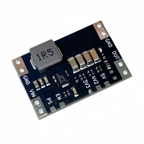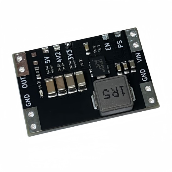


XL63020-3.3/4.2/5.0V lithium battery/USB automatic lifting booster power supply module single-chip microcomputer power supply
This module adopts TI lifting voltage special chip TPS63020 lifting voltage voltage scheme. The output ripples are low, the performance is stable, the switching frequency is as high as 2.4MHz, and most of the output current is greater than 900mA.It is very suitable for various 3.3V 5V single -chip microcomputers to use carp batteries and USB for power supply. Similarly, the module reserves two modes: conventional working mode and power -saving mode for users to choose from.
The module is a typical lifting voltage structure. The input voltage range is 1.8-5.5V output current can meet the power supply requirements of STM32, ESP32, 51 single-chip microcomputer.The battery life of the input device such as batteries.
Introduction to parameters
Module type: lifting pressure power supply
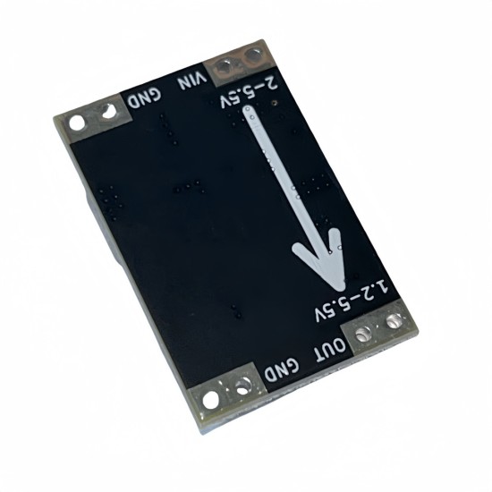
Input voltage: DC 1.8-5.5V
(3.7V input) Output current: 3. 3V@1.3A / 4.2V@1A / 5V@0.9A output voltage: DC 3.3 / 4.2 / 5V
Switch frequency: about 2.4MHz
Work mode: Conventional/power -saving mode adjustment method: selection of jump pads, 3.3/4.2/5V
Module interface: Large -area pad (can also be connected to 2.54mm needle) Module Size: 17.4x26.2mm (manual measurement, existing deviation)
The user can customize the output voltage, and the short 3V3 pad outputs 3.3V voltage. In the same way, 4V2 pad output 4.2V, prohibit short -circuit multiple pads at the same time
Point definition:
Vin: Power input Positive Electrical Electrical Election, 1.8-5.5V
GND: Input and output negative electrode, shared
VOUT: Power output end, 3.3/4.2/5V
PS: Short -connected pad to make power saving mode
EN: Hanging can enable, low -level disability
Voltage jump pad: Short connection enables the corresponding voltage, prohibit disconnect or short connecting multiple
About output
The module is non -high -power design, but it is suitable for the power supply of the vast majority of single -chip microcomputers. Therefore, do not exceed the limit value that has been tested below, especially the load current.
The MIN voltage of the module can reach 1.8V, but the output power is less at low voltage. Therefore, we recommend referring to the MAX output current under different voltage inputs below.
Regarding the power -saving mode and output indicator light, because the static power consumption is still high in the existence of the indicator light, if the user needs to save the power mode and does not need the indicator light, it can remove the indicator light to reduce the static power consumption.The user can customize the output voltage, and the short 3V3 pad outputs the 3.3V voltage of the 3.3V voltage. The 4V2 pad outputs 4.2V. It is forbidden to short -circuit pads at the same time.Then you can cut off the three jump pads, welded the two 0603 resistors in the ADJ position, default welded R1 02, and reserve R2 for users
For the load, it is not recommended to be a sensitive load with a high power. The emotional load startup current is large and easy to burn the module. The rated current meets the conditions but it is easy to appear that the module cannot provide the launch current required for the load.
Precautions
1. Do not contact the module component with a small resistance or other resistance value. The contact will cause the module to be in the normal working situation and the output voltage fluctuates significantly.2. When a large current measurement voltage is measuring voltage, please use a shorter/thick wire for connection (line resistance will affect the measurement voltage), or directly measure the terminal, otherwise the voltage measurement will be inaccurate.
3. The non -module limit value of the above parameters, but leaves the parameters indicated after there is a certain amount of room. The marking parameters are obtained through the long -distance running test. It is recommended to use it in the above parameters.4. In order to prevent the client's hand touch the module circuit due to static electricity, the chip is destroyed, so try to avoid the module touched the resistance capacity of the chip near the chip when the module is power -on.5. The module cannot reach the test value in the high temperature environment. The higher the temperature, the weaker the output ability.
6. Do not quickly connect the input -end power supply when the module is loaded, especially the power supply clip probe to quickly touch back and forth on the pads, which can easily cause the internal disorders of the moduleOpen the power, first connect the GND port when connected.
| Product Attributes | |
| Brand | Other/Other |
| Output Voltage | 0.1 |
Unlimited Blocks, Tabs or Accordions with any HTML content can be assigned to any individual product or to certain groups of products, like entire categories, brands, products with specific options, attributes, price range, etc. You can indicate any criteria via the advanced product assignment mechanism and only those products matching your criteria will display the modules.
Also, any module can be selectively activated per device (desktop/tablet/phone), customer login status and other criteria. Imagine the possibilities.
$1.77
Price in reward points: 1
- Stock: In Stock
- Model: ULJR1310
- Weight: 0.10kg


